
#### THIS IS AN IMPORTED PAGE ####
10 MHz OCXO Project
10 November 2010
I recently "won" an Isotemp 134-10 bare OCXO from China on eBay and came upon a web page by Clint KA7OEI implementing one of these into a box/case, complete with splitting amplifier and a oven control circuit.
The basic 134-10 product datasheet PDF is here.
The original web page is here but the important part of the documentation is the schematic (full size version here), re-scaled and provided here so that the correct schematic is still used to match the PCB if Clint updates his project :
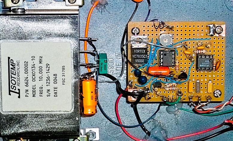
Clint built up his "controller" using perfboard (image above) but it seemed to be an ideal project to "PCB" so I used ExpressPCB to create the layout further below. Note that this single-sided board uses a mix of SMD parts (eg small 1206 resistors and 0805 capacitors) and standard parts (electros, tantalums, semiconductors etc ).
All SMDs are on the bottom ( the copper layer ) and all standard parts insert through holes from the top to be soldered on the bottom side.
There are 3 wire links involved and it is important that these be fitted, particularly the one under C101 before this electro is actually installed on the PCB.
There are also 2 zero-ohm 1206 resistors used as links on the PCB and mounted in the area of the Oven Voltage Control trimpot R119 and Q102. Note that the oven control trimpot style is a 10mm x 5mm, horizontal version, but adjust the hole positions to suit your style.
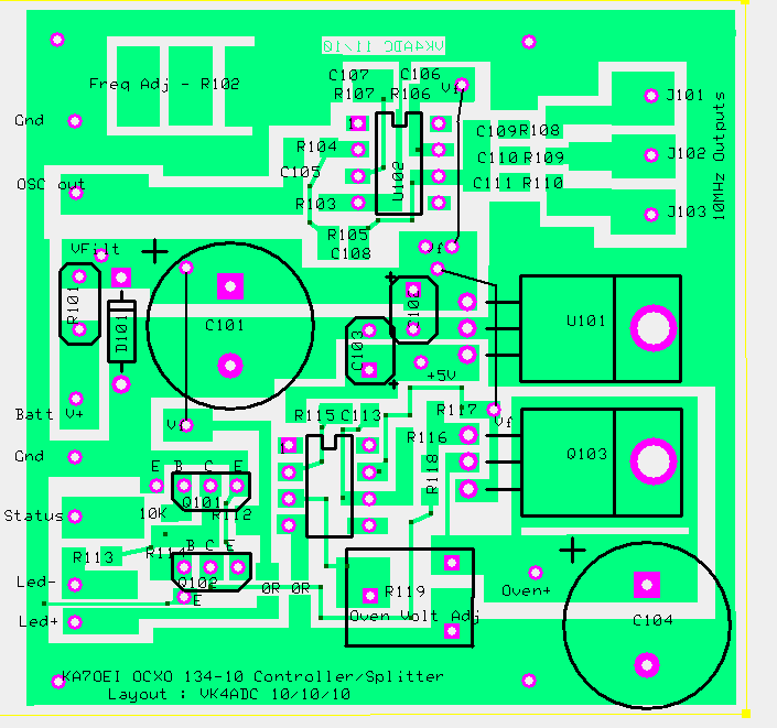
Finished board size is 70 x 67mm, only requiring a single sided PCB material.
The part codes on the layout match up with the schematic above. You can print your own PCB artwork and overlay to build up the project from, file below.
The layout on the PCB for the original 2 x 2N3904 transistors is actually B-C-E ( eg 2SC945's...) rather than the E-B-C for the 2N3904's. It is still possible to fit the E-B-C lead pattern devices by rotating the transistor by 90 degrees and shaping the leads. Just be careful when inserting these transistors that you do have the leads in the correct order before soldering them. The actual types used are not critical - any NPN switching transistor with a BVcbo of > 20V and hFE of > 100 is fine .
If necessary, Q103 can be shifted off the PCB to allow it to be better heatsink-ed. Just run the wires back to the normal pad holes in the same order. My initial idea is to use a large-ish finned TO220 style heatsink above the PCB but I will have to see how it handles the temperature rise/power dissipation long-term.
The 7805 regulator can be screwed down to the PCB but does not require any real heatsinking so just mounting by it's 3 pigtail leads is ok.
The zipped "PCB file" is here but you will need to download ExpressPCB to be able to use it. When you go to use the artwork printed from it, make sure you can read the "VK4ADC 11/10" correctly so that you know you have it the right way around before you expose the "photo board" through it.
There should be enough PCB area along the top and bottom to establish a couple of mounting screws.... You can always add some more "meat" along each side of the PCB if you want more mounting hole space.
Note that there are a couple of rectangular "pads" near the top LHS to allow the fitting of the 5K 10 turn trimming potentiometer (R102) for fine frequency adjustment. If you mount this part elsewhere, simply don't use these pads.
My method of calibrating frequency is to use the old Lissajous pattern technique on my dual-beam oscilloscope (set in X-Y mode) with the 10 MHz from my GPSDO into one channel and the oscillator to be calibrated into the other. Adjust the frequency trimpot (R102) for an absolutely stationary pattern after the OCXO has well and truly "warmed up". Note that some of the 134-10 units have a removable screw on one side that provides access to the coarse adjustment.
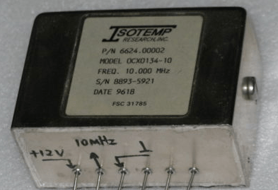
Cover screw visible on RHS.
Construction Views :
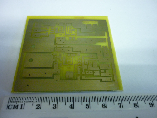
The "bare" PCB before trimming
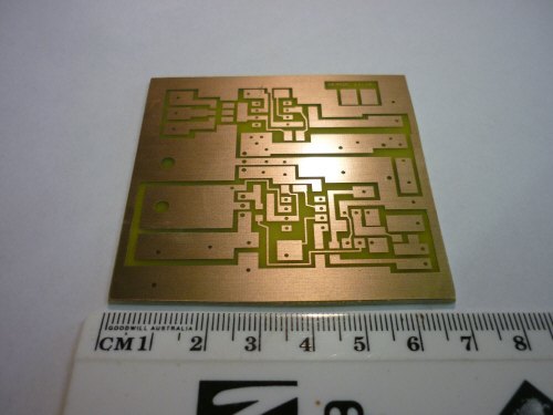
After trimming to size
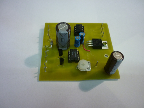
Top view. Only the FET Q103 and the poly-fuse are missing.
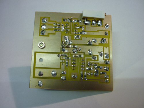
Bottom view. The multiturn trimpot at top RHS is for fine frequency trimming. All SMD parts are this side.
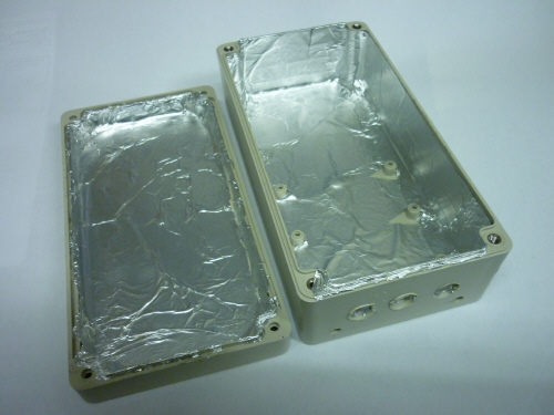
I chose to line the inside of an ABS plastic box with aluminium foil ( applied over a coat of spray glue ) because I could not readily find a suitable size diecast box - while I had the ABS box on hand.
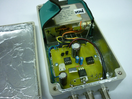
The OCXO itself is simply held in place with a cut-up mouse mat as a form of rubber shock mount. The PCB screws down on each side into the moulded plastic standoffs built into the bottom of the box.
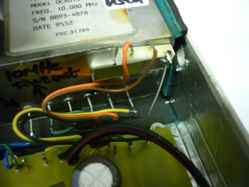
This is a close-up of the fine frequency 10 turn multi-turn trimpot and it's mounting on a tinplate z-bracket soldered to the face of the OCXO. It is accessed through a hole drilled through the side of the box. Obviously it has been moved from under the PCB.... ( as seen on the PCB photos above) and contact-adhesive glued into the Z-mount.

The view from the other end of the box showing the wiring to the 3 BNC sockets and the power cord (fig-8) DC wiring. The folded flap of mouse pad above the RHS of the OCXO simply exerts downward pressure on the OCXO case to keep it fixed in position.
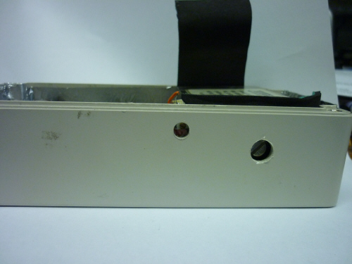
The large screw at right can be removed through it's respective hole in the side of the box and the smaller inside slotted trimmer accessed for coarse frequency adjustment - preferably with the fine trimpot near the centre of it's range - and only after the unit has stabilised.
Interestingly, my OCXO starts off 130 Hz high in frequency at dead cold. Within about 5 mins (and after the oven status LED shows that it has at least partially heated), the error is around 20-30 Hz. The frequency doesn't fully stabilise to what is probably about 0.1-0.5 Hz until 20 - 30 minutes after power is first applied.
Adjustment : Wait until properly warmed up !!!! Then, using the Lissajous pattern on the XY-scope, the fine adjustment is made carefully until the trace on the oscilloscope does not rotate. The reference signal on the other oscilloscope channel is 10.000 from my GPSDO.
My thanks to Clint for doing the "hard bit" (the electronics design) this time around.